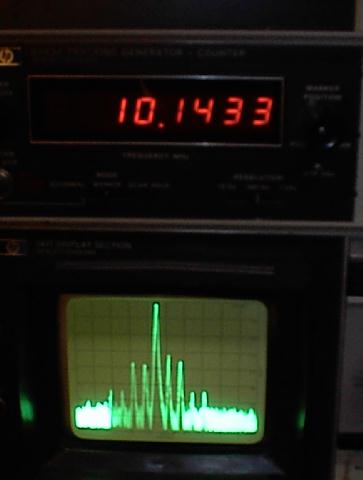
WARC-Bler spectrum at 2W output power
(HP-141T with Tracking Generator)
|
The 30M WARCbler PSK-31 Rig Conversion Kit By: Fred Spinner, W0FMS and Jeff Woods, W0ODS (C) Copyright 2001, Fred Spinner and Jeff Woods -- All Rights Reserved May 14, 2001 |
Part 3--
Other Circuit Modifications:
If the filter redesign wasn't complicated enough, the transmitter mods were even more time consuming to redesign.
Output filter section:
Original parts are a pair of 1000 pF capacitors and a 2.2 uH toroidal inductor (L2, C11 & C12).
Driver Transistor tuned feed:
Receiver input filter:
C13 and L3 must be changed to resonate on the 30 meter band.
Receiver RF Amplifier:
The RF amplifier (Q9) has been re-biased for better gain at 10 MHz and an output impedance of 180 ohms to match the new receiver filter.
Notes on Transmit Gain:
Although it initially appeared to be a trivial modification, we've spent many hours optimizing the transmit driver stage. In the process, we've learned how to use Ansoft's Harmonica SV to model RF nonlinear circuits. See David Newkirk's article in the January 2001 QST for information on this very useful design tool. Harmonica SV is about 30 MB and can be freely downloaded from the Ansoft site.
The maximum output power of the SA612 is -15 dBm at the 1 dB compression point. Our desired transmitter output power is 2W, or +33 dBm. So the transmit stage must have >48 dB gain on a single frequency. Here we run into a classic direct conversion receiver problem: how to keep a high gain stage stable. In addition, this stage must present a well-behaved termination to the transmit Cohn filter. At 80m the stages in the original Warbler have suficient gain to allow the driver stage to be swamped by a 1.5k input resistor for filter termination. An added advantage to this method is that impedance reflections from the PA stage do not affect filter performance.
At 3.6 MHz, the PA has an input impedance of 7.4 -j3.3 Ohms and a measured gain of 24 dB. At 10.14 MHz, the input Z is 5.7 +j15 Ohms and only 15 dB gain. These values were measured by an HP8753D vector network analyzer. We could find no model information for the 2SC2166C transistors; so we resorted to the good old "empirical method." No Gummel-Poon models were injured in the creation of this transmitter.
At first glance, it appeared that T1 was being used to transform the collector impedance of Q4 to a level commensurate with the PA transistor's input impedance. This is not the case as T1 is a 1:1:1 transformer. L1 and C10 together form an L-match to accomplish the impedance transformation from 400 Ohms to 5.7 Ohms.
Unfortunately, we were still many dB short of having adequate performance. The 2N4401 transistors used in the driver stage weren't as 'hot' at 30m as they were at 80m, and they had to produce 9 dB more gain to make up for the gain slope of the 2SC2166C finals. After many tries (and lifted PCB traces...) we gave up and installed a pair of MPS5179 transistors. Not only did they provide more gain, the real circuit perfomance was much closer to that predicted by Harmonica. The 2N4401 is rated as a switching transistor, thus the RF critical parameters appear to be not as well controlled in manufacturing. At 50 Cents for the pair of MPS5179s, it's really worth using good parts!
The bias of Q3 was changed to allow more quiescent current through its collector. Our first iteration included a bypass capacitor for R8, but we found that instability resulted from the lack of emitter degeneration.
The limiting factor in this design is the SA612. It is only capable of limited output power and is also the limiting factor in spectral purity. The transmitter RF stages add very little distortion to the transmitted signal. 3rd order IMD products are 30 dB down at the output of the SA612 and 30 dB down at the antenna jack. It should be noted that the best IMD perfomance is obtained at the 2 watt output level. At this point, the desired signal is at its highest with respect to the suppressed carrier and, thus, at its cleanest. The easiest way to set power is to advance the audio drive until the power supply current is maximized, then back off a little. If the audio drive is advanced beyond the optimum point, the power supply curent and power output will actually drop. This occurrs because the SA612 begins to generate proportionally more harmonic energy, which is attenuated by the transmit filter. The total available power from the '612 remains the same, so the desired tone's power has to drop. The Alpha model draws about 300 mA at 13.8 volts while producing 2W output power.
WARC-Bler spectrum at 2W output power
(HP-141T with Tracking Generator)
NEXT: WARCbler Conversion Kit/Parts List/Conversion Instructions