Antenna was designed by Kent Britian, WA5VJB, and full credit (and blame)
belongs to him on this design!
This antenna is ideal for rovers, and is good for a fixed station on
a budget. It can be built for around $15-20 (1999 dollars).
The boom material typically is wood, 1/2" by 3/4" sold in home centers as "flat pine molding". 3/4" x 3/4" solid molding is usuable as well. There is little reason why fiberglass tubing wouldn't work as well.
Outdoor varnish, paint or deck stain will work to weatherproof the antenna. Put a dab of RTV over the coax connection after verifying the SWR of the antenna.
Elements can be secured as WA5VJB suggests, with epoxy or RTV, or alternatively as I do: I file a small groove around each element very close to where it protrudes out of the 1/2" wooden boom (on each side), and force on "push-nuts" (also called "speed-nuts") on each side of the element for a positive hold.
On the center conductor, solder a small brass washer or nut onto the "J" shaped side of the element before mounting, and clip the "push-nut" to the other side upon mounting on the boom.
I usually also wind a small loop of the RG-58 coax into a small RF choke under the feedpoint to act as a balun. WA5VJB states that this step is unnecessary, but I'm a purist...
| Reflector | Driven | Director 1 | Director 2 | Director 3 | Director 4 | Director 5 | Director 6 | Director 7 | Director 8 | |
| Length | 6.2 | * | 5.6 | 5.5 | 5.5 | 5.4 | 5.3 | 5.2 | 5.1 | 5.1 |
| Spacing | 0 | 2.4 | 3.9 | 5.8 | 9.0 | 12.4 | 17.4 | 22.4 | 27.6 | 33.0 |
* See diagram above for details. 9.10" Total length.
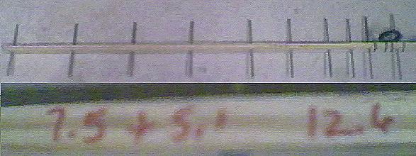
UPDATE: This antenna was measured at the CSVHF Society 2000 Meeting in Winnipeg, Manitoba, Canada by Kent Britian himself. It made a pretty good account of itself, and actually would have won an award if they actually would have had some for antennas this year!!
Here is a picture of the constructed antenna, with a close up of Kent's handwriting (fuzzy but readable-- cheap webcam photo): The measured gain was 12.6 dBd, not bad for a $10 antenna constructed in about an hour.
The solution was fairly simple: I downloaded a freeware CAD program
CADSTD from http://www.cadstd.com,
and drew a little CAD template up that had all the element lengths,
and four templates that are taped together for the spacing.
This was then printed on a HP LaserJet 4, actual size, to form a cutting
and drilling template.
The result was a remarkably accurate antenna.
The CADSTD data file is here: 902/903 CadStd data
CADSTD also exports to HPGL and DXF formats, but I can not read either of them back in. Here is the template in the other formats: HPGL, DXF.
Note, I never did get the text to work right in the CAD program (no labels in the drawing), so the elements are from top to bottom, Reflector, Driven (with the loops and the bend location in them, and the mounting center location), then all of the Directors. The templates start from top to bottom, Reflector at top, last directors at bottom.