Antenna was designed by Kent Britian, WA5VJB, and full credit (and blame)
belongs to him on this design!
This antenna is ideal for rovers, and is good for a fixed station on
a budget. It can be built for around $15-20 (1999 dollars).
The boom material typically is wood, 1/2" by 3/4" sold in home centers as "flat pine molding". 3/4" x 3/4" solid molding is usuable as well. There is little reason why fiberglass tubing wouldn't work as well.
Outdoor varnish, paint or deck stain will work to weatherproof the antenna. Put a dab of RTV over the coax connection after verifying the SWR of the antenna.
Elements can be secured as WA5VJB suggests, with epoxy or RTV, or alternatively as I do: I file a small groove around each element very close to where it protrudes out of the 1/2" wooden boom (on each side), and force on "push-nuts" (also called "speed-nuts") on each side of the element for a positive hold.
On the center conductor, solder a small brass washer or nut onto the "J" shaped side of the element before mounting, and clip the "push-nut" to the other side upon mounting on the boom.
I usually also wind a small loop of the RG-58 coax into a small RF choke under the feedpoint to act as a balun. WA5VJB states that this step is unnecessary, but I'm a purist...
Element Lengths and Spacings in Inches:
144 MHz. This antenna is peaked for 144.2 MHz but performance
is still good at 146.52 (emergency use only!) Driven element dimensions
are L = 38.5" and H = 1.0" Elements are 1/8" diameter.
| 144 MHz | Reflector | Driven | Director 1 | Director 2 | Director 3 | Director 4 | |
| 3 Element | Length | 41.00 | 37.00 | ||||
| 3 Element | Spacing | 0.00 | 8.50 | 20.00 | |||
| 4 Element | Length | 42.00 | 37.50 | 33.00 | |||
| 4 Element | Spacing | 0.00 | 8.50 | 19.25 | 40.50 | ||
| 6 Element | Length | 40.50 | 37.50 | 36.50 | 36.50 | 32.75 | |
| 6 Element | Spacing | 0.00 | 7.50 | 16.50 | 34.00 | 52.00 | 70.00 |
222 MHz. This antenna is peaked for 222.1 MHz but performance
bearly changes at 223.5 MHz. Driven element dimensions are L = 24.5" and
H = 1.0" Elements are 3/16" diameter.
| 222 MHz | Reflector | Driven | Director 1 | Director 2 | Director 3 | Director 4 | |
| 3 Element | Length | 26.00 | 23.75 | ||||
| 3 Element | Spacing | 0.00 | 5.50 | 13.50 | |||
| 4 Element | Length | 26.25 | 24.10 | 22.00 | |||
| 4 Element | Spacing | 0.00 | 5.00 | 11.75 | 23.50 | ||
| 6 Element | Length | 26.25 | 24.10 | 23.50 | 23.50 | 21.00 | |
| 6 Element | Spacing | 0.00 | 5.00 | 10.75 | 22.00 | 33.75 | 45.50 |
432 MHz. This antenna is peaked for 432.1 MHz. At this frequency,
this antenna is getting very practical and easy to build. Driven element
dimensions are L = 13.0" and H = 3/8" Elements are 1/8" diameter.
| 432 MHz | Reflector | Driven | Dir 1 | Dir 2 | Dir 3 | Dir 4 | Dir 5 | Dir 6 | Dir 7 | Dir 8 | Dir 9 | |
| 6 Element | Length | 13.50 | 12.50 | 12.00 | 12.00 | 11.00 | ||||||
| 6 Element | Spacing | 0.00 | 2.50 | 5.50 | 11.25 | 17.50 | 24.00 | |||||
| 8 Element | Length | 13.50 | 12.50 | 12.00 | 12.00 | 11.00 | 12.00 | 11.25 | ||||
| 8 Element | Spacing | 0.00 | 2.50 | 5.50 | 11.25 | 17.50 | 24.00 | 30.75 | 38.00 | |||
| 11 Element | Length | 13.50 | 12.50 | 12.00 | 12.00 | 11.00 | 12.00 | 12.00 | 11.75 | 11.75 | 11.00 | |
| 11 Element | Spacing | 0.00 | 2.50 | 5.50 | 11.25 | 17.50 | 24.00 | 30.75 | 38.00 | 45.50 | 53.00 | 59.50 |
902/903 MHz. This was the first antenna I built using the antenna to control the driven element impedance. The 2 1/2' length has proven practical, so I haven't built any other versions. Driven element dimensions are L = 5.7" and H = 1/2" Elements are 1/8" diameter.
| 902/903 MHz | Reflector | Driven | Director 1 | Director 2 | Director 3 | Director 4 | Director 5 | Director 6 | Director 7 | Director 8 |
| Length | 6.2 | * | 5.6 | 5.5 | 5.5 | 5.4 | 5.3 | 5.2 | 5.1 | 5.1 |
| Spacing | 0 | 2.4 | 3.9 | 5.8 | 9.0 | 12.4 | 17.4 | 22.4 | 27.6 | 33.0 |
* See diagram above for details. 9.10" Total length.
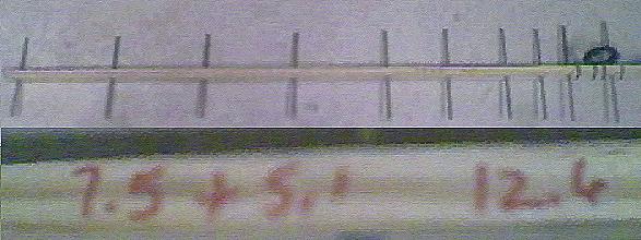
UPDATE: My antenna was measured at the CSVHF Society 2000 Meeting in Winnipeg, Manitoba, Canada by Kent Britian himself. It made a pretty good account of itself, and actually would have won an award if they actually would have had some for antennas this year!!
Here is a picture of the constructed antenna, with a close up of Kent's handwriting (fuzzy but readable-- cheap webcam photo): The measured gain was 12.6 dBd, not bad for a $10 antenna constructed in about an hour.
1296 MHz. This antenna is the veteran of several "Grid Peditions"
but I have yet to actually measure the gain. Dimensions must be followed
with great care. The driven element is small enough to allow 0.141 semi-rigid
coax to be used instead of RG-58. Silicon Bronze welding rod was used for
the elements but any material can be used. Driven element dimensions are
L = 4.0" and H = 1/2" Elements are 1/8" diameter.
| 1296 MHz | Reflector | Driven | Dir 1 | Dir 2 | Dir 3 | Dir 4 | Dir 5 | Dir 6 | Dir 7 | Dir 8 | |
| 10 Element | Length | 4.30 | 3.90 | 3.80 | 3.75 | 3.75 | 3.65 | 3.60 | 3.60 | 3.50 | |
| 10 Element | Spacing | 0.00 | 1.70 | 2.80 | 4.00 | 6.40 | 8.70 | 12.20 | 15.60 | 19.30 | 23.00 |